
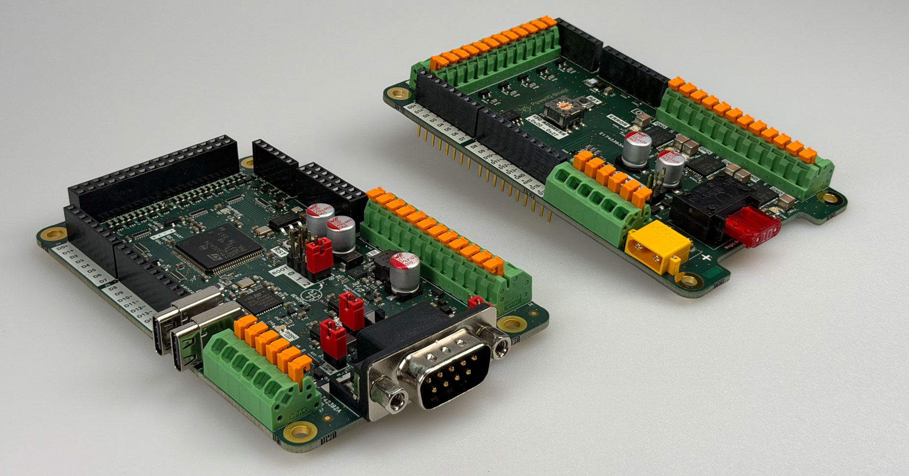
Introducing ARDEP
Automotive development has always meant proprietary tools, expensive licenses, and hardware that was not built for the realities of the job. ARDEP, the Automotive Rapid Development Platform, is our answer to that.
Developed by Frickly Systems in collaboration with Mercedes-Benz, ARDEP is a fully open-source hardware and software platform designed to give automotive engineers what they actually need: a fast, robust, and reusable foundation that does not get in the way.
Built for Automotive Environments
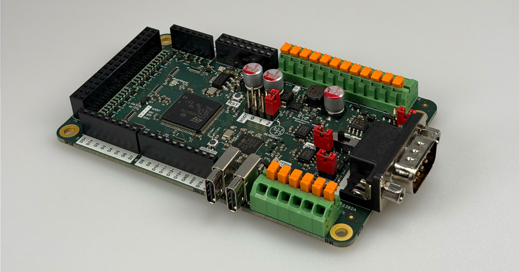
Standard development boards are not designed for automotive supply voltages, transient conditions, or the mechanical realities of a test bench or vehicle installation. ARDEP is. The board accepts input voltages from 5V to 48V via its main supply terminals, with overvoltage protection via a 51V TVS diode. USB-C is also supported for bench use. The board comes with quality connectors, spacers and mounting screws included, so it stays put whether you are on a bench or inside a vehicle.
CAN-FD and LIN Out of the Box
No shields. No adapter libraries. No cables that fall off. ARDEP ships with two CAN-FD capable transceivers and one LIN transceiver built in. Both share a single DB-9 connector in accordance with the Vector pinout, making it a drop-in replacement in existing toolchain setups. CAN Channel B is permanently connected to the DB-9. CAN Channel A and LIN are both also accessible via spring contact terminals. A hardware switch (SW1) routes either CAN-A to DB-9 pins 2 and 7, or LIN to DB-9 pin 7. Each CAN channel includes a common mode choke, ESD protection, and a hardware-configurable 120-ohm termination. The LIN transceiver can be software-configured for master or slave mode.
And because ARDEP can flash other devices over CAN, it fits naturally into modern zonal E/E architectures where a central node manages distributed hardware.
A Software Stack That Scales
The firmware is built on Zephyr RTOS, a mature open-source real-time operating system with a large ecosystem already used in serious production environments. Zephyr is moving toward safety certification, which means your prototype does not hit a dead end when it is time to think about production. UDS diagnostics (ISO 14229) are included out of the box, along with DFU firmware update support over CAN and USB. Boards ship with a production-ready bootloader and firmware loader pre-installed, supporting both UDS DFU via CAN and USB DFU for application updates.
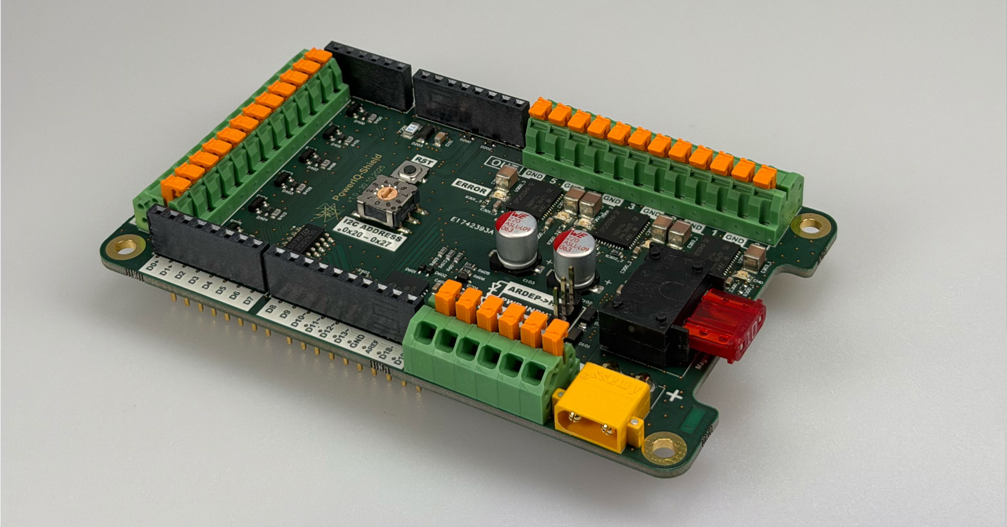
Power IO Shield
The optional Power IO Shield extends the platform for switching high-power loads. It adds six 48V-capable high-side output drivers rated at 3A continuous per channel and 10A total across all six channels, plus six 48V-capable inputs. Each output driver includes per-channel LED indicators for overcurrent and overtemperature faults, plus I2C diagnostic feedback to the mainboard that pinpoints which driver IC faulted. The shield is designed to switch automotive loads like relays, solenoids, and actuators directly from software.
Open Source. All of It.
Hardware design files, firmware, documentation: everything is published on GitHub under a permissive Apache license. No lock-in, no license fees, no asking permission. The project is hosted under the Mercedes-Benz GitHub organization, reflecting the open-source commitment that drove the project from the start.
GitHub: github.com/mercedes-benz/ardep
Documentation: mercedes-benz.github.io/ardep
Main Board
Input Voltage (Vin): 5V to 48V via main terminals. Protected by 51V TVS diode and 1A slow-blow fuse.
USB Power: 4.75V to 5.25V via USB-C
Internal 5V rail: Max 500mA total (shared across 5V and 3.3V outputs and MCU)
3.3V output: Available on Arduino header and 32-pin connector, 200mA poly fuse per group
5V output: Available on pin headers, 200mA poly fuse
LIN supply input (VLIN): 0V to 24V external (extendable to 36V with different ESD protection)
CAN: 2x CAN-FD transceivers with ESD protection, common mode choke, 120-ohm termination. DB-9 Vector pinout.
LIN: 1x LIN transceiver, software-selectable master/slave mode
GPIO: 3.3V logic level
MCU: STM32 (ARM Cortex-M)
Connectivity: USB-C, CAN-FD x2, LIN x1, SPI, I2C, UART, Arduino headers
Debug: On-board debugger with UART connection (from v2.0.0)
Firmware: Zephyr RTOS, UDS (ISO 14229), DFU over CAN and USB
License: Apache 2.0 (hardware and software)
Power IO Shield
Supply voltage: Up to 48V
Outputs: 6x high-side drivers, 3A continuous per channel, 10A total
Inputs: 6x 48V-capable digital inputs
Diagnostics: Per-channel overcurrent and overtemperature fault detection via I2C
Output driver IC: IPS2050HQ-32 smart high-side switch
GitHub: github.com/mercedes-benz/ardep
Documentation: mercedes-benz.github.io/ardep